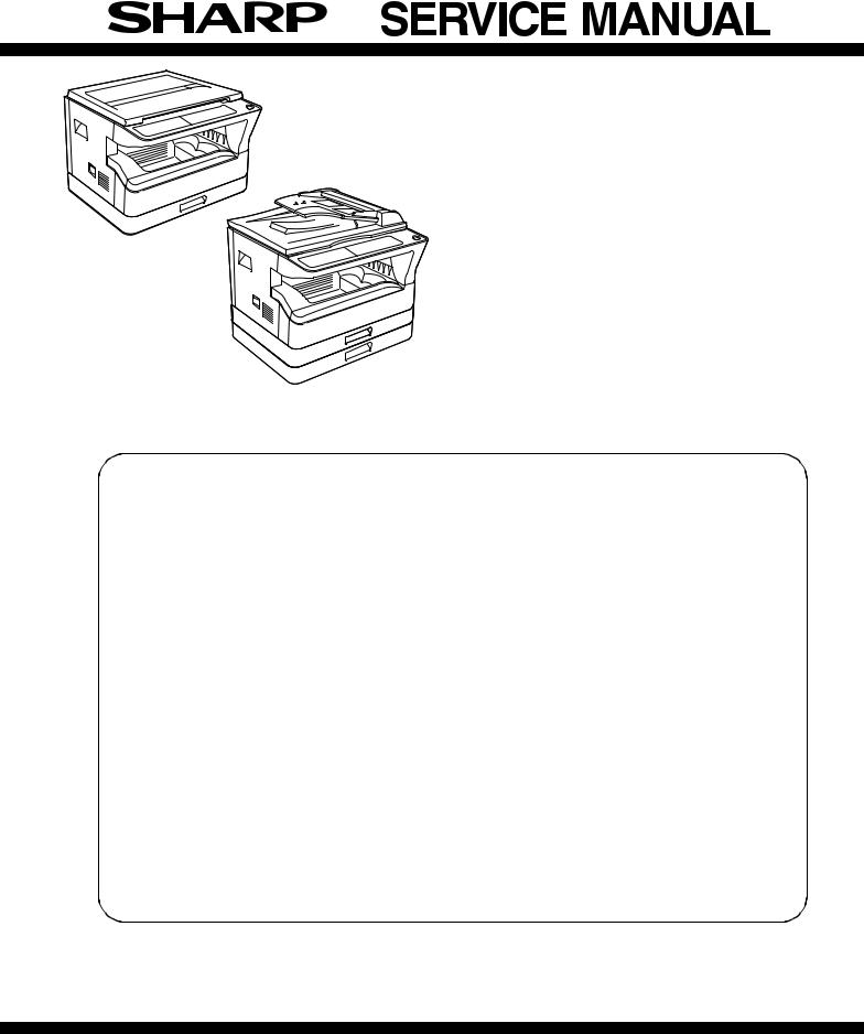
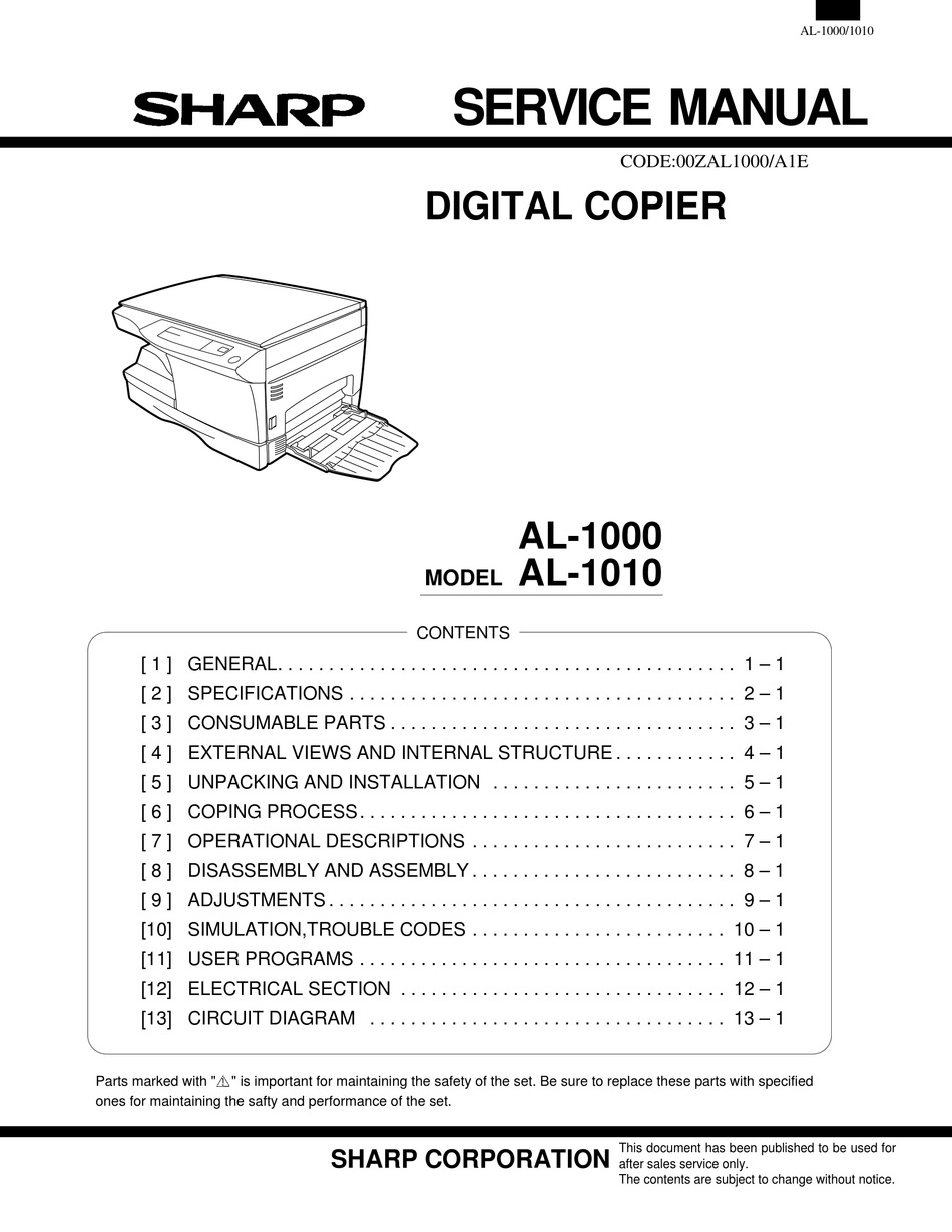
View Sharp MX-4140N / MX-4141N / MX-5140N / MX-5141N (serv.man7) Service Manual online

Does your Sharp color copier need to be calibrated? As the machine begins to age, parts begin to wear and if the colors look off, then the answer is probably.
- This is a short and simple video on accessing simulation mode on SHARP MX series printers. This method can be used for MX-M354N, MX-1810U, MX-2010U, MX-2310U.
- Motor Poligon SHARP AR5726 AR5731 AR5626 AR5631 MASQ6NF1RS🔥🔥 Y.
- Service Manual Sharp AR-5520 AR-5516 AR-5520S AR-5516S AR-5520D AR-5516D AR-5520N AR-5516N Model AR-5518; This manual is in the PDF format and have detailed Diagrams, pictures and full procedures to diagnose and repair your Sharp copier. You can print, zoom or read any diagram, picture or page from this Service Manual.
NOTE FOR SERVICING
1. Precautions for servicing . . . . . . . . . . . . . . . . . . . . . . . . . i
2. Warning for servicing . . . . . . . . . . . . . . . . . . . . . . . . . . . . i
3. Note for installing site. . . . . . . . . . . . . . . . . . . . . . . . . . . . i
4. Note for handling PWB and electronic parts . . . . . . . . . .ii
5. Note for repairing/replacing the LSU . . . . . . . . . . . . . . . iii
6. Note for handling the drum unit, the transfer unit,
the developing unit. . . . . . . . . . . . . . . . . . . . . . . . . . . . . iii
7. Screw tightening torque . . . . . . . . . . . . . . . . . . . . . . . . . iii
PRODUCT OUTLINE
1. System diagram . . . . . . . . . . . . . . . . . . . . . . . . . . . . . . 1-1
2. Main Function . . . . . . . . . . . . . . . . . . . . . . . . . . . . . . . 1-2
3. Option list . . . . . . . . . . . . . . . . . . . . . . . . . . . . . . . . . . . 1-2
1. System diagram . . . . . . . . . . . . . . . . . . . . . . . . . . . . . . 1-1
2. Main Function . . . . . . . . . . . . . . . . . . . . . . . . . . . . . . . 1-2
3. Option list . . . . . . . . . . . . . . . . . . . . . . . . . . . . . . . . . . . 1-2
SPECIFICATIONS
1. Basic specifications . . . . . . . . . . . . . . . . . . . . . . . . . . . 2-1
2. Copy functions . . . . . . . . . . . . . . . . . . . . . . . . . . . . . . . 2-7
3. Printer function. . . . . . . . . . . . . . . . . . . . . . . . . . . . . . . 2-8
4. Image send function. . . . . . . . . . . . . . . . . . . . . . . . . . . 2-9
5. Power consumption . . . . . . . . . . . . . . . . . . . . . . . . . . 2-10
6. Dimensions and Weight . . . . . . . . . . . . . . . . . . . . . . . 2-10
7. Ambient conditions. . . . . . . . . . . . . . . . . . . . . . . . . . . 2-10
CONSUMABLE PARTS
1. Supply system table. . . . . . . . . . . . . . . . . . . . . . . . . . . 3-1
2. Maintenance parts list . . . . . . . . . . . . . . . . . . . . . . . . . 3-2
3. Definition the developer/drum life end . . . . . . . . . . . . . 3-5
4. Production number identification . . . . . . . . . . . . . . . . . 3-6
5. Environmental conditions . . . . . . . . . . . . . . . . . . . . . . . 3-6
EXTERNAL VIEW AND INTERNAL STRUCTURE
A. Identification of each section and functions . . . . . . . . . 4-1
A. Identification of each section and functions . . . . . . . . . 4-1

B. External view . . . . . . . . . . . . . . . . . . . . . . . . . . . . . . . . 4-1
C. Internal operation parts . . . . . . . . . . . . . . . . . . . . . . . . 4-2
D. I/F Connectors . . . . . . . . . . . . . . . . . . . . . . . . . . . . . . . 4-3
E. Operation panel . . . . . . . . . . . . . . . . . . . . . . . . . . . . . . 4-4
DSPF . . . . . . . . . . . . . . . . . . . . . . . . . . . . . . . . . . . . . . 4-5
G. RSPF . . . . . . . . . . . . . . . . . . . . . . . . . . . . . . . . . . . . . . 4-7
H. Sensor, Detector . . . . . . . . . . . . . . . . . . . . . . . . . . . . . 4-9
Switch . . . . . . . . . . . . . . . . . . . . . . . . . . . . . . . . . . . . 4-11
Clutches and solenoids . . . . . . . . . . . . . . . . . . . . . . . 4-12
K. Motors . . . . . . . . . . . . . . . . . . . . . . . . . . . . . . . . . . . . 4-13
L. Rollers . . . . . . . . . . . . . . . . . . . . . . . . . . . . . . . . . . . . 4-15
M. Lamps . . . . . . . . . . . . . . . . . . . . . . . . . . . . . . . . . . . . 4-17
N. Fans and filters . . . . . . . . . . . . . . . . . . . . . . . . . . . . . 4-18
O. PWB/Memory device . . . . . . . . . . . . . . . . . . . . . . . . . 4-19
Fuses and Thermostats . . . . . . . . . . . . . . . . . . . . . . . 4-21
ADJUSTMENTS AND SETTINGS
1. General . . . . . . . . . . . . . . . . . . . . . . . . . . . . . . . . . . . . 5-1
2. Adjustment item list . . . . . . . . . . . . . . . . . . . . . . . . . . . 5-1
3. Details of adjustment . . . . . . . . . . . . . . . . . . . . . . . . . . 5-3
1. General . . . . . . . . . . . . . . . . . . . . . . . . . . . . . . . . . . . . 5-1
2. Adjustment item list . . . . . . . . . . . . . . . . . . . . . . . . . . . 5-1
3. Details of adjustment . . . . . . . . . . . . . . . . . . . . . . . . . . 5-3
SIMULATION
1. General and purpose . . . . . . . . . . . . . . . . . . . . . . . . . . 6-1
2. Starting the simulation . . . . . . . . . . . . . . . . . . . . . . . . . 6-1
3. List of simulation codes . . . . . . . . . . . . . . . . . . . . . . . . 6-3
4. Details of simulation . . . . . . . . . . . . . . . . . . . . . . . . . . . 6-9
TROUBLE CODE
1. Trouble code and troubleshooting . . . . . . . . . . . . . . . . 7-1
2. JAM and troubleshooting . . . . . . . . . . . . . . . . . . . . . . 7-36
1. Trouble code and troubleshooting . . . . . . . . . . . . . . . . 7-1
2. JAM and troubleshooting . . . . . . . . . . . . . . . . . . . . . . 7-36
FIRMWARE UPDATE
1. Outline . . . . . . . . . . . . . . . . . . . . . . . . . . . . . . . . . . . . . 8-1
2. Update procedure . . . . . . . . . . . . . . . . . . . . . . . . . . . . 8-1
1. Outline . . . . . . . . . . . . . . . . . . . . . . . . . . . . . . . . . . . . . 8-1
2. Update procedure . . . . . . . . . . . . . . . . . . . . . . . . . . . . 8-1
MAINTENANCE
1. Works necessary when executing the maintenance . . . 9-1
2. Display of maintenance execution timing. . . . . . . . . . . 9-2
1. Works necessary when executing the maintenance . . . 9-1
2. Display of maintenance execution timing. . . . . . . . . . . 9-2

3. Maintenance list . . . . . . . . . . . . . . . . . . . . . . . . . . . . . . 9-3
4. Details . . . . . . . . . . . . . . . . . . . . . . . . . . . . . . . . . . . . . 9-7
4. Details . . . . . . . . . . . . . . . . . . . . . . . . . . . . . . . . . . . . . 9-7
1. Disassembly of Units . . . . . . . . . . . . . . . . . . . . . . . . . 10-1
2. Disassembly and assembly of each unit . . . . . . . . . 10-34
1. HDD/SD card memory map . . . . . . . . . . . . . . . . . . . . 11-1
2. Necessary steps when replacing the PWB . . . . . . . . 11-3
3. Necessary works and notes for replacement of the mirror-
2. Necessary steps when replacing the PWB . . . . . . . . 11-3
3. Necessary works and notes for replacement of the mirror-
ing kit HDD . . . . . . . . . . . . . . . . . . . . . . . . . . . . . . . . . 11-8
4. Note for installing and repairing the mirroring kit . . . 11-11
1. General . . . . . . . . . . . . . . . . . . . . . . . . . . . . . . . . . . . 12-1
2. Details and operation procedures . . . . . . . . . . . . . . . 12-1
2. Details and operation procedures . . . . . . . . . . . . . . . 12-1
1. Operation panel section . . . . . . . . . . . . . . . . . . . . . . . 13-1
2. DSPF section . . . . . . . . . . . . . . . . . . . . . . . . . . . . . . . 13-3
3. RSPF section . . . . . . . . . . . . . . . . . . . . . . . . . . . . . . . 13-9

4. Scanner section . . . . . . . . . . . . . . . . . . . . . . . . . . . . 13-15
5. Manual paper feed section. . . . . . . . . . . . . . . . . . . . 13-17

6. Tray paper feed section . . . . . . . . . . . . . . . . . . . . . . 13-19
7. Paper transport section . . . . . . . . . . . . . . . . . . . . . . 13-22
8. Paper exit section. . . . . . . . . . . . . . . . . . . . . . . . . . . 13-23
9. ADU section . . . . . . . . . . . . . . . . . . . . . . . . . . . . . . . 13-24
10. LSU section . . . . . . . . . . . . . . . . . . . . . . . . . . . . . . . 13-26
11. OPC Drum section . . . . . . . . . . . . . . . . . . . . . . . . . . 13-29
12. Toner supply section . . . . . . . . . . . . . . . . . . . . . . . . 13-34
13. Developing section. . . . . . . . . . . . . . . . . . . . . . . . . . 13-36
14. Transfer section . . . . . . . . . . . . . . . . . . . . . . . . . . . . 13-38
15. Fusing section . . . . . . . . . . . . . . . . . . . . . . . . . . . . . 13-42
Simulation For Sharp Copier Lsu University
16. Fan and filter . . . . . . . . . . . . . . . . . . . . . . . . . . . . . . 13-45
17. Operations and specifications of counters . . . . . . . . 13-46
Simulation For Sharp Copier Lsu Health
1. Block diagram . . . . . . . . . . . . . . . . . . . . . . . . . . . . . . 14-1
2. Power line diagram . . . . . . . . . . . . . . . . . . . . . . . . . 14-10
3. Actual wiring chart . . . . . . . . . . . . . . . . . . . . . . . . . . 14-15
4. Signal list . . . . . . . . . . . . . . . . . . . . . . . . . . . . . . . . . 14-31
2. Power line diagram . . . . . . . . . . . . . . . . . . . . . . . . . 14-10
3. Actual wiring chart . . . . . . . . . . . . . . . . . . . . . . . . . . 14-15
4. Signal list . . . . . . . . . . . . . . . . . . . . . . . . . . . . . . . . . 14-31
[15] TOOL LIST. . . . . . . . . . . . . . . . . . . . . . . . . . . . . . . . . . . . 15-1
Simulation For Sharp Copier Lsu Tech
Click on the first or last page to see other MX-4140N / MX-4141N / MX-5140N / MX-5141N (serv.man7) service manuals if exist.